


The first thing I did was plug in the trainer cable (a standard 3.5mm
audio cable) and probed the other end with my scope. I did this both
with and without the RF module plugged in. The main power switch is
left in the off position while using the trainer cable.
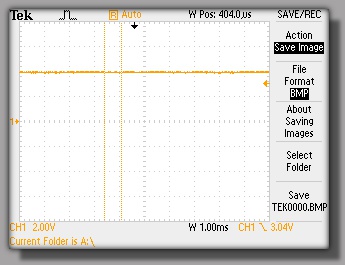
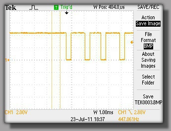
RF module unplugged
RF module plugged in
As can be seen from the scope captures, when the module is plugged
in the output PWM signal is gone, but a DC level is still present.
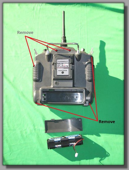
The next step was to take the radio apart so I could take a look at the signals inside driving the RF module.
The next step was to take the radio apart so I could take a look at the signals inside driving the RF module.
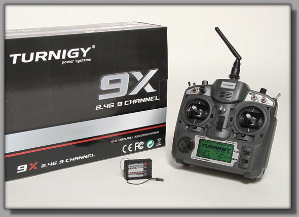
The Turnigy 9x, also sold under various other brand names, is a
great radio for the money. In addition to being decent right out of
the box it's highly hackable with numerous mods, including custom
firmware, available on the web. It's not all rainbows and Mickey
Mouse smiles though with several annoyances and bugs being
present in the stock system. Fortunately most are fixable with a little
investigation on the internets.
One such annoyance manifests itself when trying to use the trainer cable for either controlling a PC simulator or for buddy box training in the field. The stock system requires the user to unplug the RF module and leave it dangling by the antenna cable. This is not only inconvenient, but also increases the risk of damaging the tiny cable. A quick search of the googles leads to several descriptions and videos of how to fix the problem involving cutting a trace and installing a resister in line. Although there was plenty of feedback indicating the fix worked, I wanted to dig into it a little further and see exactly what was going on. Here is what I found.
One such annoyance manifests itself when trying to use the trainer cable for either controlling a PC simulator or for buddy box training in the field. The stock system requires the user to unplug the RF module and leave it dangling by the antenna cable. This is not only inconvenient, but also increases the risk of damaging the tiny cable. A quick search of the googles leads to several descriptions and videos of how to fix the problem involving cutting a trace and installing a resister in line. Although there was plenty of feedback indicating the fix worked, I wanted to dig into it a little further and see exactly what was going on. Here is what I found.
Turnigy 9x V.2 - Trainer Port Fix
RF module unplugged
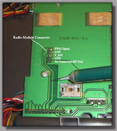
Remove the battery and the 6
screws holding the back on.
Once the back was off I found the
RF module connector and through
a combination of signal tracing and
probing with a scope determined
the pinout.
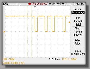
PWM Signal at the trainer cable output.
RF module plugged in
PWM Signal at the RF module connector.
After finding the RF module pin out I measured various signals with
the scope and determined the following:
a) When the trainer cable is plugged in, no power is sent to the RF module regardless of the position of the main power switch.
b) The PWM signal on the trainer cord is not directly connected to the PWM signal feeding the RF module. Some sort of buffer circuit appears to be present.
c) Even when the trainer cord PWM signal is not present (RF module installed), the RF module PWM signal is present although at a reduced level.
d) The problem persists regardless of the position of the main power switch.
Although several details remain unanswered such as the specifics of the
buffer circuit, this was enough information to determine what was
happening with reasonable confidence.
Because the RF module is unpowered, the PWM signal is being loaded down. Having live signals driving unpowered circuits is generally avoided unless special design steps have been taken. Driving unpowered circuits can result in anything from the benign to the catastrophic if a latch up condition occurs. In this case the results seem to be harmless to the circuit although the signal is being pulled down due most likely to input clamping diodes or ESD circuitry in the RF module. This reduction in signal level is possibly enough to prevent the buffer circuit from triggering. The signal level is still over 3V which leads me to believe the buffer is some sort of comparator with a fairly high threshold voltage, perhaps a convenient 3.3V level from a supply used to power other parts of the circuit. Unless someone takes the time to trace out the internals of the Tx it's unlikely we'll ever know.
The most common fix on the internet is to add a 1K resister in line with the signal driving the RF module. It turns out this is common practice as an inexpensive means to isolate a driving circuit from a unpowered load. It has the effect of limiting the current into the load to prevent damage and latch up conditions. In our case it will also prevent our signal from being pulled below the threshold level. There are some precautions that need to be considered however so we'll look at those as we implement the fix.
The Investigation:
The Fix:
The fix is to cut the trace that connects the PWM signal to the RF
module and install a resister in line to help isolate the driving circuit
from the unpowered load. It's fairly straight forward so lets get started.
Once the back of the radio has been removed (see above) the trace feeding the PWM signal to the RF module must be located and cut. Feel free to unplug the connector holding the back half of the Tx to the front half as this will make your job easier. Just remember to plug it back in when your done.
The cut can be made with a standard hobby knife, but care must be used to prevent damaging nearby traces. The width of the cut you make will depend on what type of resister you plan on installing. Most internet examples use a 1/4 watt leaded resistor. In that case the width of the cut is not critical, just make sure you've isolated the two parts of the trace. Use an ohm meter if you have one to make sure. In my case I used a 0603 surface mount resister so the width of the cut was more important so the resistor could span the cut. It was also necessary to scrape the solder mask off the traces where the cut had been made to give something for the solder to stick to. In the case of a leaded resistor you can solder to the actual connector pins on each end of the trace.
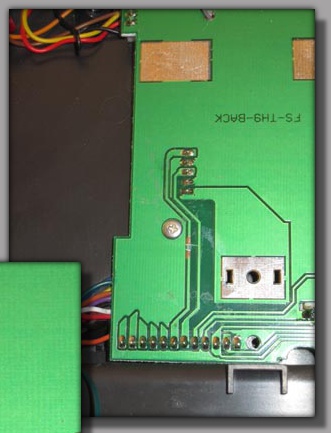
<- The trace to be cut
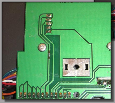
Trace cut and silkscreen removed. ->
<- The completed mod.
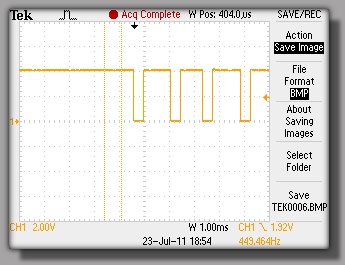
Once the mod was made it was time to test things out. I plugged in the
trainer cable with the RF module installed and looked at the output on a
scope. We have a nice looking signal!
One of the potential problems with inserting a resistor in line between the signal source and load is you create a voltage drop across the resistor. If the voltage drop is large enough there won't be enough signal level for the RF module to operate properly when in normal operation mode (non-trainer mode). I unplugged the trainer cable and turned on the radio to measure the PWM signal level at the RF module connector. I was getting a 4V signal. There was a little drop, but more than enough signal for the module to operate normally. It should be noted that this signal level is highly dependent on the input impedance of the RF module. If a different module such as the FrySky is being used and it has a lower input impedance, the signal level will be further reduced. The solution is to use a smaller value for the series resistor. Based on the measurements I've seen I see no reason why a value of 500 ohms wouldn't work. I'll look into this if/when I install a different RF module.
One of the potential problems with inserting a resistor in line between the signal source and load is you create a voltage drop across the resistor. If the voltage drop is large enough there won't be enough signal level for the RF module to operate properly when in normal operation mode (non-trainer mode). I unplugged the trainer cable and turned on the radio to measure the PWM signal level at the RF module connector. I was getting a 4V signal. There was a little drop, but more than enough signal for the module to operate normally. It should be noted that this signal level is highly dependent on the input impedance of the RF module. If a different module such as the FrySky is being used and it has a lower input impedance, the signal level will be further reduced. The solution is to use a smaller value for the series resistor. Based on the measurements I've seen I see no reason why a value of 500 ohms wouldn't work. I'll look into this if/when I install a different RF module.
Now that the repair is done it's time to put the Tx back together.
Remember to plug the connector back in that hooks the back case to
the front. Also be careful re-installing the screws as the plastic is easy
to strip out.
I've been using my radio now for several days as a controller for a PC simulator and everything has been working great. I haven’t had a chance to use the radio in a buddy box configuration yet but have no reason to believe it wouldn't work just fine.
Enjoy, BW
I've been using my radio now for several days as a controller for a PC simulator and everything has been working great. I haven’t had a chance to use the radio in a buddy box configuration yet but have no reason to believe it wouldn't work just fine.
Enjoy, BW
Signal level at RF module
after fix.
Output of Trainer cable
after fix.
All Content Copyright Brian and Carol Wolfe 2010, 2011.